
How to Choose the Right Latching Relay
Choosing the right Latching Relay begins with understanding the load, switching environment, and required operating life. A latching relay stays in its last position without continuous coil power. That feature can reduce energy use and limit heat inside compact control panels.
Relay application engineer Michael A. Schuster offers a practical reminder: “Select the relay for the real load, not the number printed on the datasheet.” The exact quotation should be verified against the original technical source. Still, the principle is valuable. A motor, heater, LED driver, and signal circuit can behave very differently during switching.
Look closely.
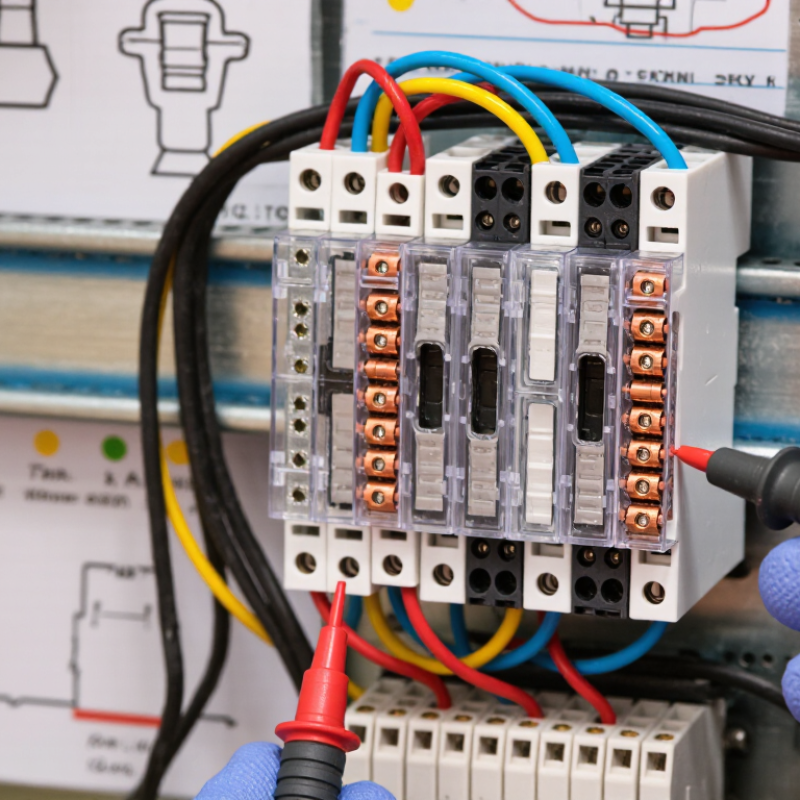
Contact rating is only one part of the decision. Check the coil voltage, pulse duration, contact material, insulation resistance, bounce time, and expected switching frequency. For a battery-powered controller, measure the reset pulse at the relay coil. For an industrial cabinet, inspect temperature rise after repeated cycles. Small details matter.
A magnetic latching relay may suit systems that need stable states during power loss. A mechanically latching design may offer dependable position retention, but its drive circuit needs careful polarity control. Wiring mistakes can damage the coil or leave the relay in the wrong state.
Do not choose by price alone. Compare verified test data, manufacturer reputation, environmental ratings, and lifecycle evidence. Some specifications look impressive but lack realistic load conditions. That is where judgment becomes necessary. The best choice is usually the relay that matches the complete application, not the most powerful component on the shelf.
Define the Application Requirements for a Latching Relay
How to Choose the Right Latching Relay
Define the Application Requirements for a Latching Relay
Start by describing the relay’s actual job, not only its voltage rating. A latching relay keeps its contact position after the coil pulse ends. This can reduce standby energy in battery-powered equipment. Record the load type, switching voltage, current, inrush current, and required contact arrangement. Resistive heaters and motors create very different stresses.
Measure the operating environment carefully. Note the temperature range, humidity, vibration, dust, and available installation space. Define how often the relay will switch each day. Also specify the pulse voltage, pulse duration, and reset method. A control circuit may need separate set and reset coils, or a single coil with reversed polarity. That choice affects wiring, driver design, and fault behavior.
Think about failure conditions before selecting a part. Ask what should happen after power loss, a stuck command, or an incomplete pulse. In practical panel testing, contact bounce and electrical noise can cause unexpected transitions. Use suitable suppression and verify the relay with the real load, not a small laboratory lamp. Check the datasheet’s electrical life, mechanical life, insulation ratings, and derating information. I often find one requirement missing: the expected state after maintenance. That detail deserves a written decision. A relay may meet every nominal rating yet perform poorly in a hot enclosure. Recheck the assumptions.
| Application Requirement | What to Define | Representative Values or Ranges | Selection Guidance |
|---|---|---|---|
| Load Type | Determine whether the relay will switch resistive, inductive, capacitive, motor, lamp, or electronic loads. | Resistive, inductive, capacitive, DC motor, AC motor, LED driver, solenoid | Contact ratings are application-dependent. Inductive and motor loads can produce substantially higher switching stress than resistive loads. |
| Load Voltage | Specify the normal operating voltage and the highest possible voltage, including transients. | Common systems include 5 V, 12 V, 24 V, 48 V DC and 120/230 V AC | Choose contacts with an appropriate voltage rating and adequate insulation. DC interruption is generally more demanding than AC interruption at the same nominal voltage. |
| Load Current | Define steady-state current, inrush current, starting current, and the minimum current that must be switched reliably. | Steady-state current from signal levels to several amperes; inrush may be several times higher | Check both maximum switching current and minimum recommended load. A relay rated for a high resistive load may require derating for motors, lamps, and capacitive power supplies. |
| Contact Configuration | Identify the required number of poles and whether normally open, normally closed, or changeover contacts are needed. | SPST-NO, SPST-NC, SPDT, DPDT and multi-pole configurations | Use normally open contacts for a default-off circuit. Use changeover contacts when the application must select between two circuits or states. |
| Latching Mechanism | Choose between single-coil and dual-coil operation based on the available control signals and power strategy. | Single-coil: polarity reversal; dual-coil: separate SET and RESET pulses | A single-coil design can reduce pin count, while a dual-coil design can simplify control logic. Confirm the required pulse polarity and sequencing. |
| Coil or Set/Reset Voltage | Match the control voltage to the relay coil and account for supply tolerance, driver voltage drop, and temperature effects. | Common nominal values include 3, 5, 6, 9, 12 and 24 V DC | The guaranteed operate voltage must be compatible with the lowest available control voltage, while the maximum permissible voltage must not be exceeded. |
| Pulse Duration | Define the minimum and maximum control-pulse width available from the controller. | Typically a few milliseconds to several tens of milliseconds; verify the device specification | The pulse must be long enough to complete reliable transfer but short enough to prevent unnecessary coil heating. Do not assume a latching relay can accept continuous coil power. |
| Power Consumption | Calculate the energy available for each switching event and the total energy budget in battery or energy-harvesting systems. | Pulse power depends on coil resistance and control voltage; holding power is normally not required after latching | Latching relays can reduce standby consumption because no continuous coil current is needed to maintain the contact state. |
| Switching Frequency | Specify expected operations per hour, day, or service life, including changes caused by abnormal conditions. | From occasional operation to frequent automated switching; life ratings are load-dependent | Compare the mechanical life and electrical life separately. Electrical life usually decreases as switched voltage, current, inrush, and arc energy increase. |
| Contact Material | Consider the load current, switching voltage, environmental conditions, and minimum-load requirements. | Typical contact systems use silver-based alloys; special materials may be used for low-level or high-inrush loads | Contact material affects weld resistance, oxidation behavior, arc resistance, and performance at low signal levels. Follow the relay manufacturer’s load guidance. |
| Insulation and Safety | Define required coil-to-contact insulation, contact-to-contact insulation, dielectric withstand, and creepage and clearance distances. | Requirements depend on working voltage, overvoltage category, pollution degree, and applicable safety standard | For mains circuits, verify reinforced or basic insulation requirements and use a relay with appropriate approvals for the end application. |
| Operating Temperature | Specify the minimum and maximum ambient temperature, as well as heat generated by nearby components. | Common industrial ranges are approximately −40 °C to +85 °C; wider ranges may be available | Coil resistance, operate characteristics, contact capacity, and service life can change with temperature. Apply the specified derating curve where required. |
| Environment | Assess humidity, dust, chemicals, vibration, shock, altitude, and the need for an enclosed or sealed relay. | Ventilated, dust-protected, or sealed construction depending on the installation | Sealed construction can improve resistance to moisture and contaminants. Confirm that the enclosure and terminal system suit the actual environment. |
| Control Circuit Protection | Define how the controller will protect the driver from voltage spikes and incorrect SET/RESET commands. | Flyback diode, TVS clamp, Zener clamp, current-limited driver, or polarity-reversing H-bridge | A suppression method must be compatible with the relay’s required release or reset behavior. Add interlocking where simultaneous SET and RESET activation is possible. |
| Mounting and Termination | Specify PCB, socket, panel, surface-mount, through-hole, screw-terminal, or wire-lead installation. | PCB, DIN-rail interface, panel-mounted, or harness-connected formats | Check terminal current capacity, creepage and clearance on the board, mechanical retention, orientation, and available installation space. |
| Default State After Power Loss | Determine whether the relay must retain its last state or move to a defined state after power is removed. | State retention is inherent to latching operation; automatic return generally requires additional circuitry | Use a latching relay when state retention without continuous power is required. Add a reset strategy if the system must start in a known safe state. |
| Reliability and Service Life | Define the required number of operations and the acceptable failure mode for the system. | Mechanical life can be much higher than electrical life; exact values depend on construction and load | Use the manufacturer’s electrical-life curves for the actual load rather than relying only on the headline mechanical-life rating. |
Related Posts
-
How to Choose the Best Lithium Iron Phosphate Battery for Your Needs?
-

Top Tips for Choosing the Right Forklift Battery for Your Needs
-

2026 Top Flow Batteries What You Need to Know
-

How Best Forklift Battery Optimizes Warehouse Efficiency with Real World Applications
-

Why Power Storage Batteries Are Essential for Sustainable Energy Solutions
-

What Is a Lithium Solar Battery and How Does It Work?